What is an aeroshell?
An aeroshell is a rigid heat-shielded shell that protects a spacecraft component from pressure, heat, and possible debris created by drag during atmospheric entry.
What does Rocket Team use aeroshells for?
Because there is not enough room inside the rocket for cameras and we need both upwards and downwards facing cameras (as opposed to outwards facing), we must place them outside the rocket’s airframe. And since you can’t just glue the cameras on the rocket and call it a day, we must make aeroshells to reduce drag and protect them.
Phoenix’s cameras are different from demo’s (bigger and needed to be housed with their PCBs), so the aeroshells needed a redesign.
PCB Aeroshell
Concept Description:
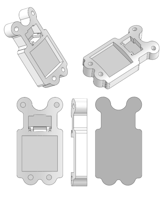
An aeroshell that houses both the camera and its PCB outside of the airframe. The shell (transparent) and holder (opaque) sandwich the airframe of the rocket with 4 screws. Holes in the airframe are made for screws, camera body, and PCB. The camera nests inside the holder and is held down by the shell. The PCB is screwed into the base of the holder. The bottom lens of the camera must be removed.
Pros:
Function as both upwards and downwards facing aeroshells
No detachment of camera from PCB necessary
PCB and camera are close together in the same holder
No need for materials besides ABS
Simply assembly
Light
Cons:
Concern for aerodynamic properties when facing upwards due to big camera and screw holes
Big holes in the airframe
Mirrored Aeroshells
Concept Description:
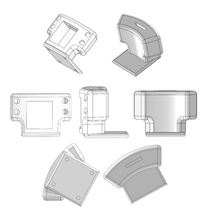
An aeroshell that holds both the camera and PCB inside the airframe. The camera lens however, is poking out. The shell (transparent) and holder (opaque) sandwich the airframe of the rocket with 4 screws. Holes in the airframe are made for screws and the camera lens. The camera is held steady by the holder, which has a slit for the ribbon cable to connect it to its PCB. The holder has a jutting plate that the PCB can be mounted and screwed onto. The bottom lens of the camera must be removed so as not to block the camera’s angled view.
The shell has a slanted wall on which a mirror will be mounted. It is set at a 53 degree angle (which will provide a 8 degree angle camera view from the airframe). Ideally, part of the aeroshell will be made of clear material.
Pros:
Function as both upwards and downwards facing aeroshells
Minimal holes in the airframe
Mirror system is a creative solution and a good design challenge
Cons:
Detachment and reconfiguration of tarsiers necessary
Difficult to access the power button on PCB
Complicated assembly
Need to integrate polycarb or other clear material so as to maximize the FOV
PCB takes up a lot of room inside the airframe
Screw placement does not offer as much stability
Holder:
Purpose: Hold the bottom of the components in place as a supportive base, often connects the airframe and the shell
Features:
Can either be designed to sandwich the airframe (as you’ve seen in these examples), or in some designs, the holder is on the outside between the shell and the airframe
The carved out base for the camera should usually be at an angle (angle depends on the camera and design and usually ranges from 5-15 degrees) so as to maximize the camera’s field of view (FOV)
Screw holes are usually threaded.

PCB Aeroshell Example

Mirrored Aeroshell Example
Shell:
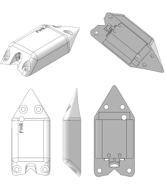
Purpose: Hold the components down, maximize the camera’s FOV, maintain an aerodynamic shape
Features:
Sometimes the shells will have stoppers coming down from their roof. This is to prevent the components from shaking and offer more stability.
It’s the component between the atmosphere and the lens, so make sure it covers as much of the camera as possible.
Screw holes on here are not usually threaded. Just make sure that there is a lip for the screw head.
If a hole for the lens is necessary, make sure it’s at the proper angle.
It’s a plus if the shell is designed so that the aeroshell can be used for upwards or downwards video.

PCB Aeroshell Example
