Chindogu Project: Create an Un-Useless Product
Ideation:
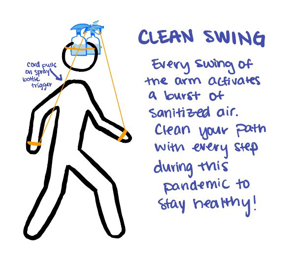
When first brainstorming, I came up with an idea to attach sanitizing spray bottles to shoes so that every time the user takes a step, the device would trigger a burst of clean air. However, this design would be more quick to wear out and doesn't reach the rest of the body as it can only spray up so far. I changed to design to be overhead and controlled by the swing of the arms. The revised design is a hat with two spray guns attached to either side. String tied to the trigger could be pulled to actuate the spray guns, leaving a nice wall of mist of water or sanitizer or both for the user to constantly walk through.
Spray Bottle Attachment
Headband Latch
Ergonomic Handles
Cardboard Layering
First Sketch Model:
For my first model, I learned a lot of things about how to construct my device while making it. I constantly tried it on in between making certain parts so that I could adjust it to my dimensions.
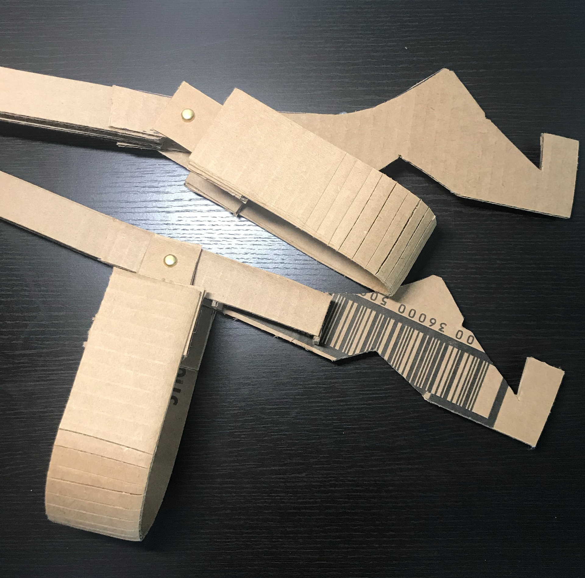
Originally, I cut the head band of the hat too small, so I improved it by creating a latch so that it could be tightened and removed easily.
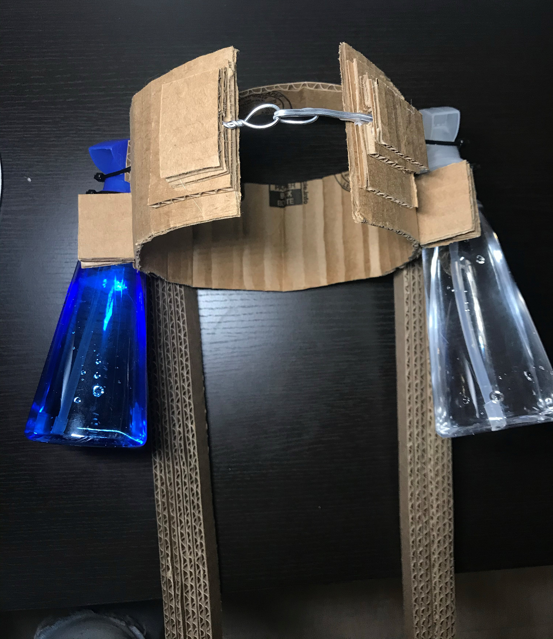
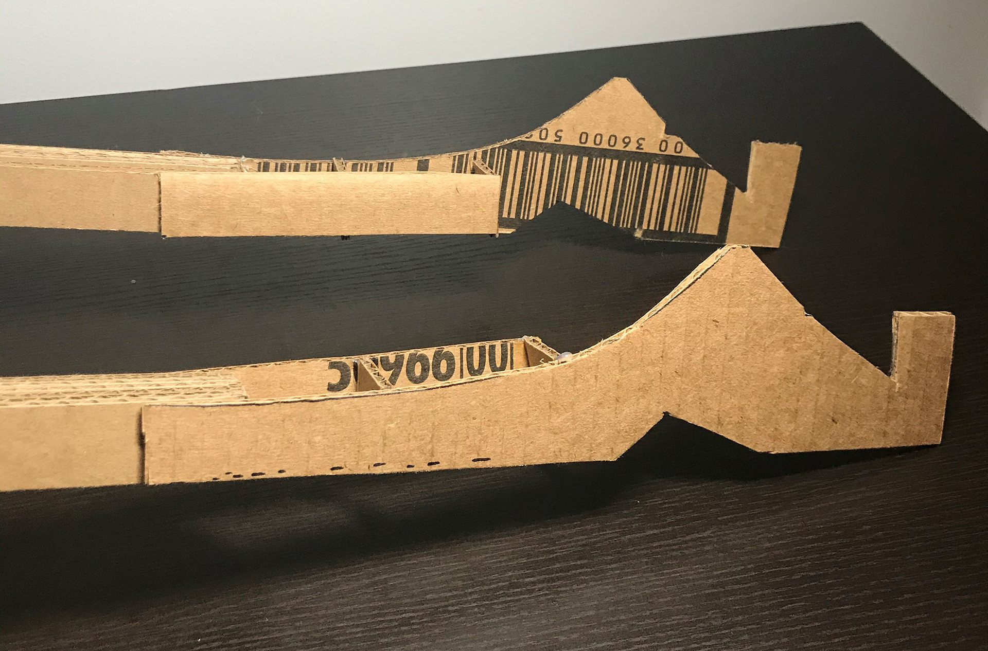
I decided that strings wouldn't provide enough torque to the trigger and decided to go with a lever design instead. I made the lever stiff by layering cardboard sheets and orienting it in the most rigid configuration so that it wouldn't bend when pulled.I eventually also found that the levers I made were too short. They only went up to my elbows and were uncomfortable to grab. I extended the lever and gave it intuitive handles shaped to be grasped in a certain way. This made the device much easier to operate.
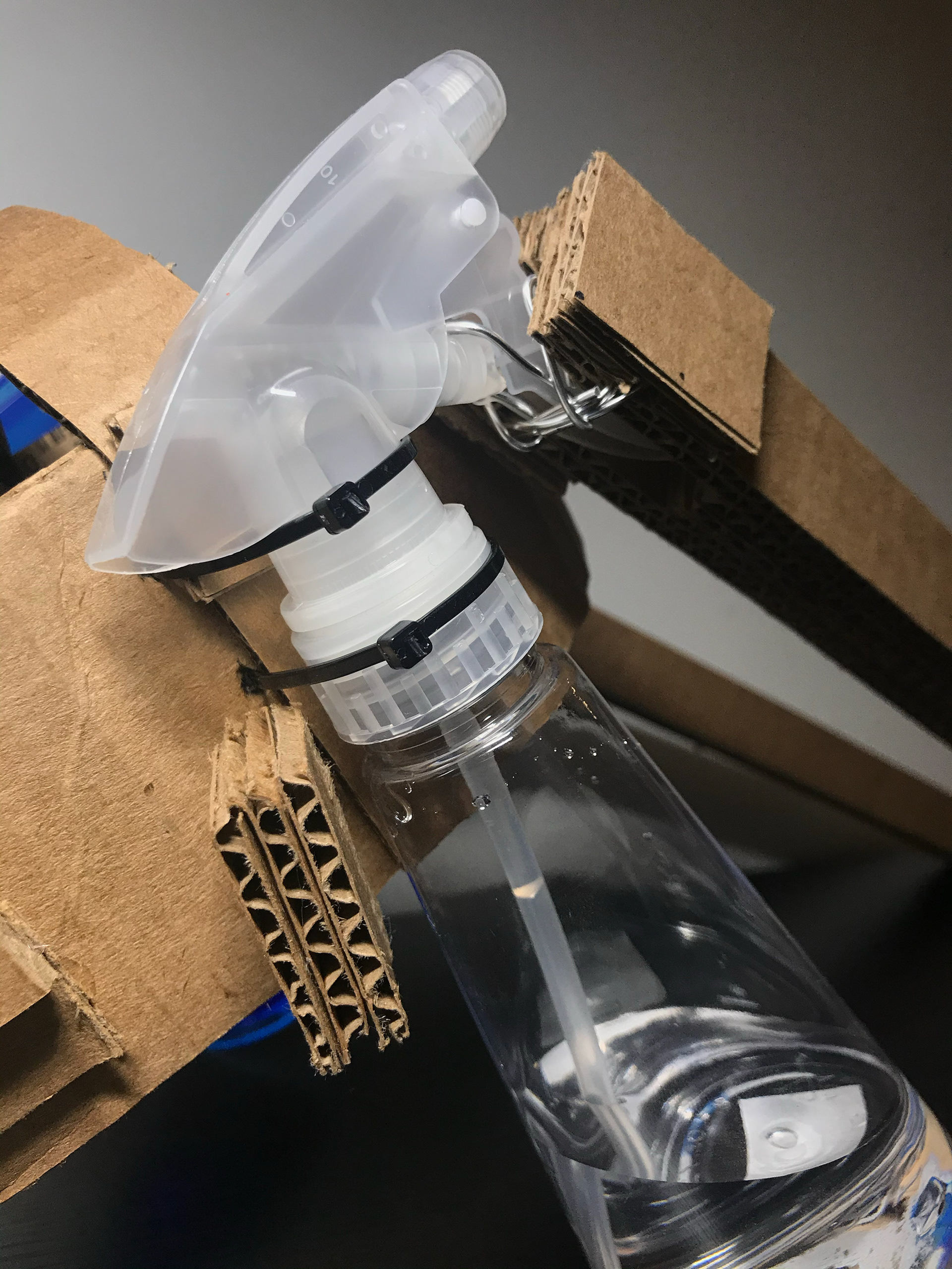
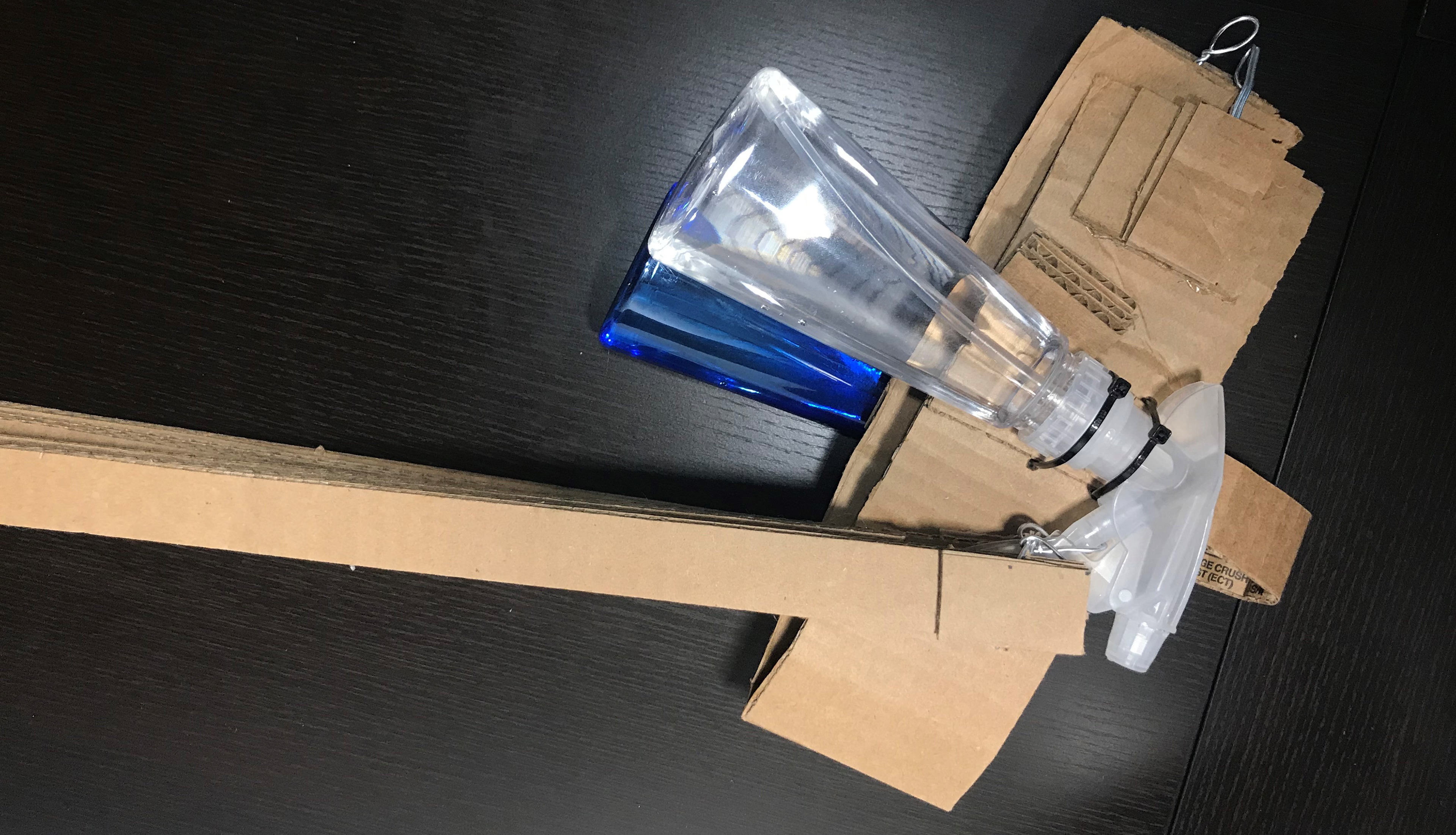
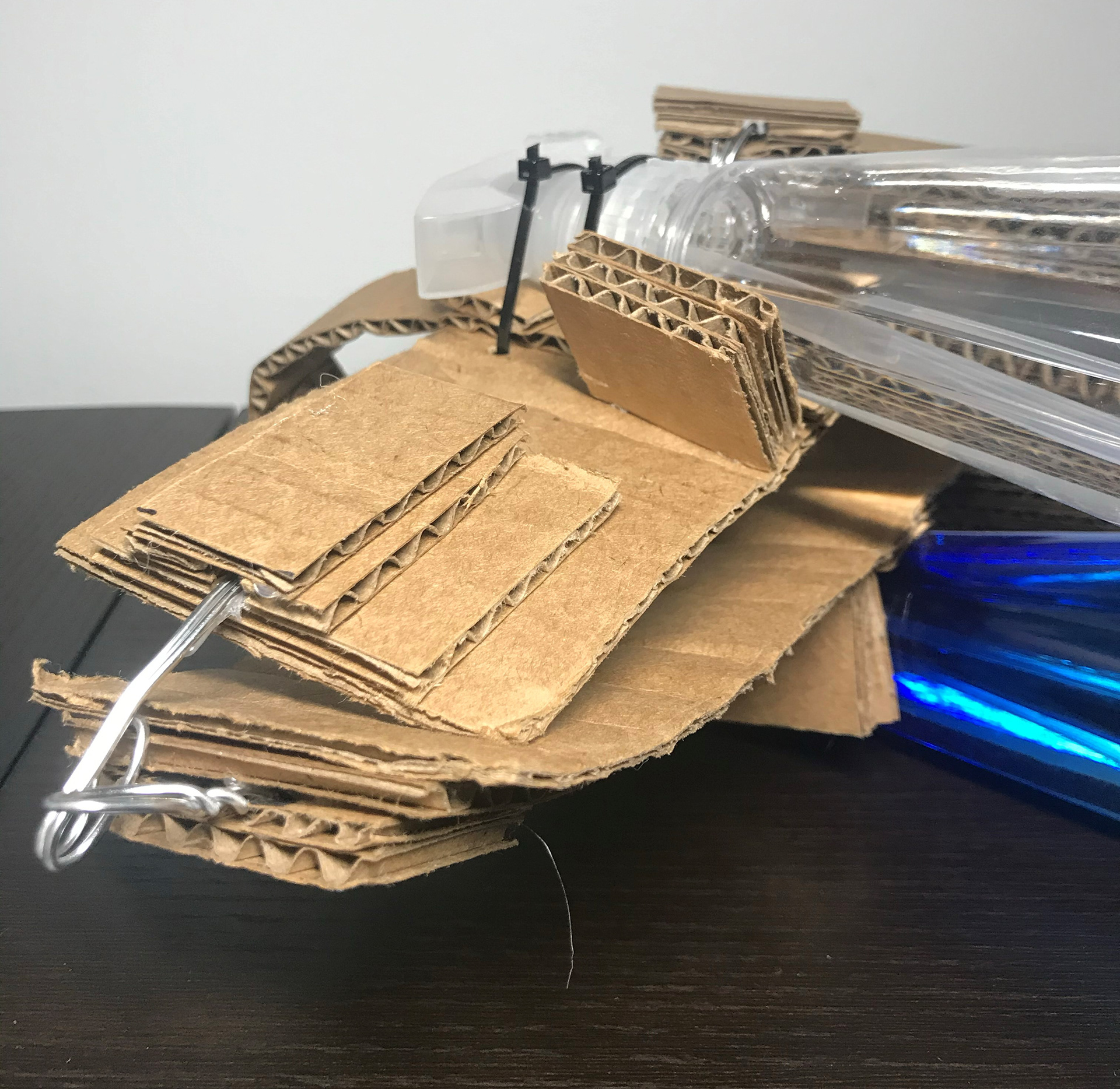
Figuring out how to attach the spray bottles to the levers and hat was also a challenge. I eventually decided on cutting a slot in the lever for the trigger to fit through and wiring different parts of the trigger to the lever. The wiring was reinforced by hot glue and more cardboard pieces to hold it down. To attach the bottles to the headband, I poked holes and ziptied the head to the bottle to it. I made sure not to attach the containers to it so that they could be removed and replaced for refills. When testing the trigger mechanism, I found that the bottle tilted forward when I pulled on the trigger, so I made back walls for the bottle so that it couldn't move back. This did well to stabilize the whole bottle.
This first iteration showed me what how to optimize design to be compatible with my body and gait. It also taught me how to use the properties of cardboard to my advantage (stiffness in one direction, buckling in another) to create the conformable and rigid parts of my device.
Back String Attachment
Folded Device
Foldable Headband
Elbow Sleeves
Second Sketch Model:
With the first sketch model, I was able to identify several issues to improve upon.
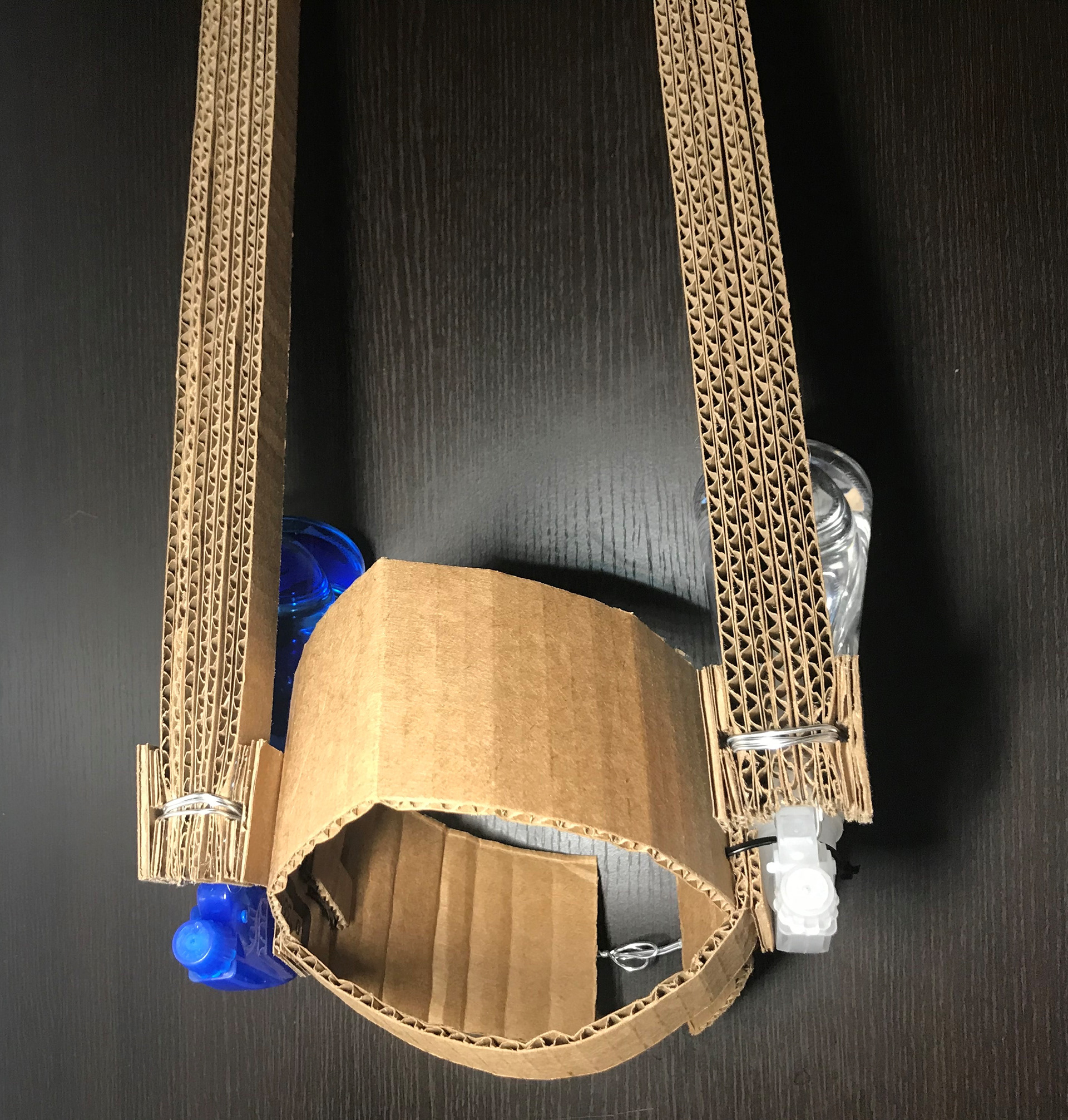
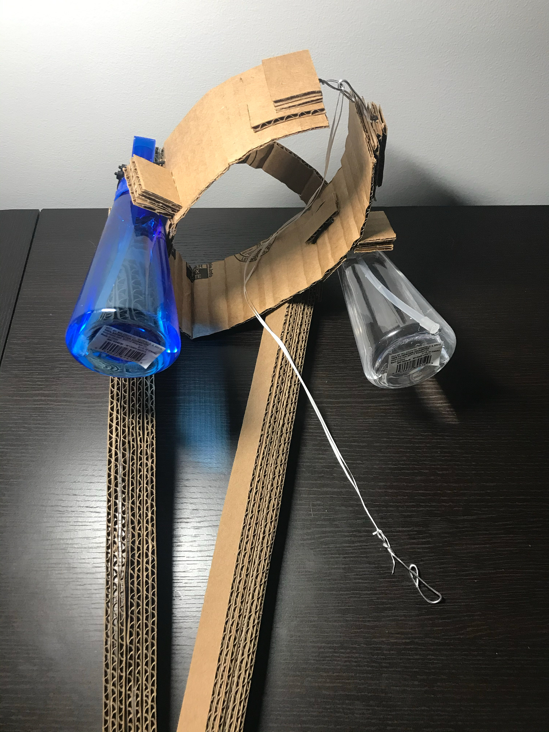
My design is chunky and I was having issues figuring out how to make it smaller for storage. I eventually discovered that I could make use of the headband latch to detach and flatten the hat part of the device! This way, the whole device can be flattened and placed somewhere a little more compact. If I had more time, I would have made the whole device modular so it could be disassembled.
Whenever I pulled on the lever, my headband would be yanked forward. This was uncomfortable because it loosened every time I swung my arms. I corrected this by adding a string that hooks the back of the headband to my pants (I used floss for this) and prevents the hat from jolting forward when pulled. This also helped me with my posture!
Another recommendation given to me was to make the device hands free in case the user wanted to carry something or use their hands while using the device. I made small loops fastened to the levers that the user can slip their arm through. I connects their upper arm to the lever so that the hands are free, but the device still moves with the swing of the arm.
This video shows how the revised device operates and how the new features contribute to its ease in use!
Throughout the second iteration, I learned more about how adjustable my design was. It was fairly easy to implement the improvements which I saw as a plus! I think that with even more time, it could be improved to be lighter, modular, and scalable, but this works-like model is a very good starting point. I shows how to integrate multiple parts of the device, how to minimize the effect of certain forces on particular parts, and how to correctly harness and restrain different motions of the body!
CAD Model & Design Analysis
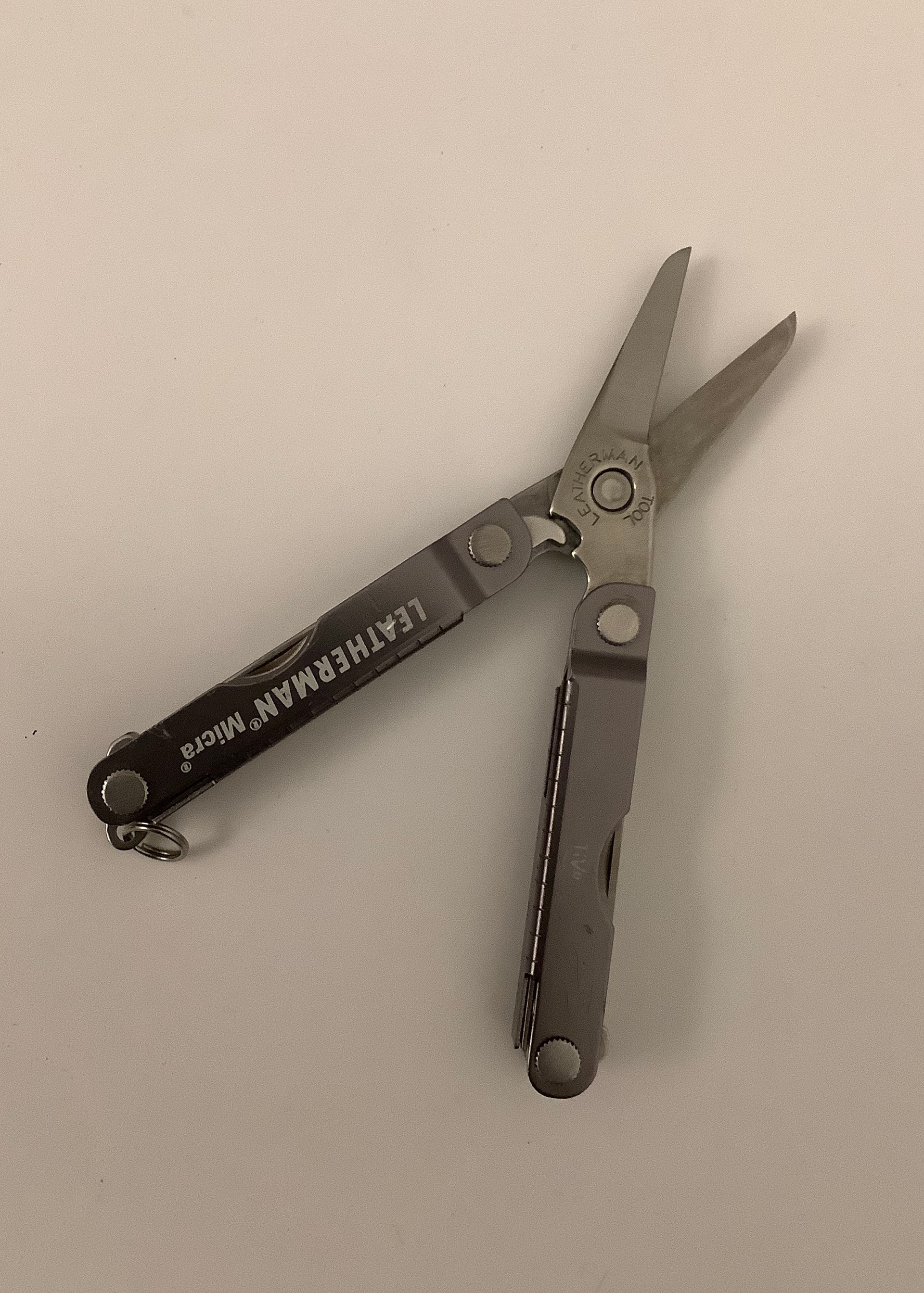
Our assignment was to take an object we owned and make a CAD replica of it! Here are pictures of mine and how they compare to the actual product.
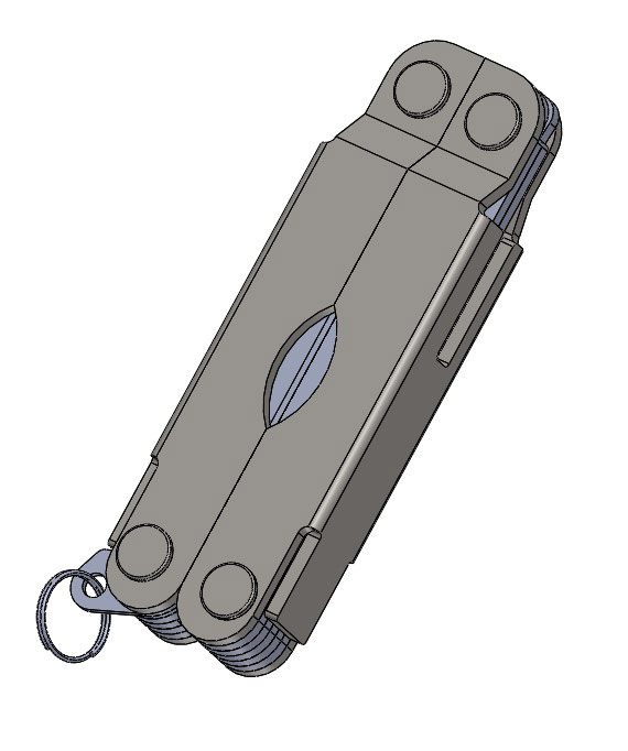
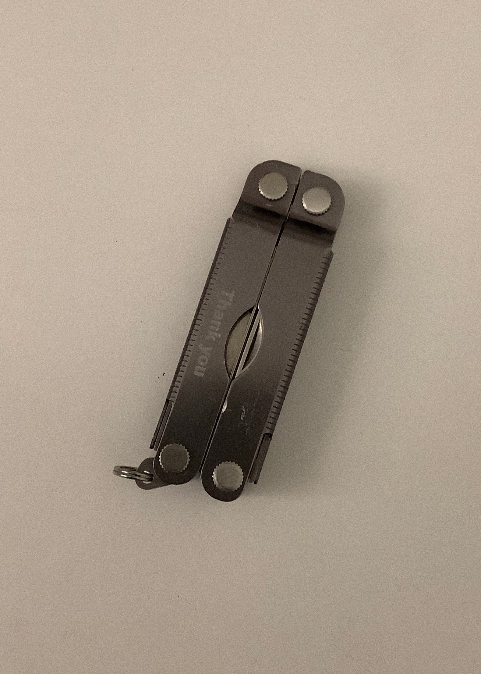
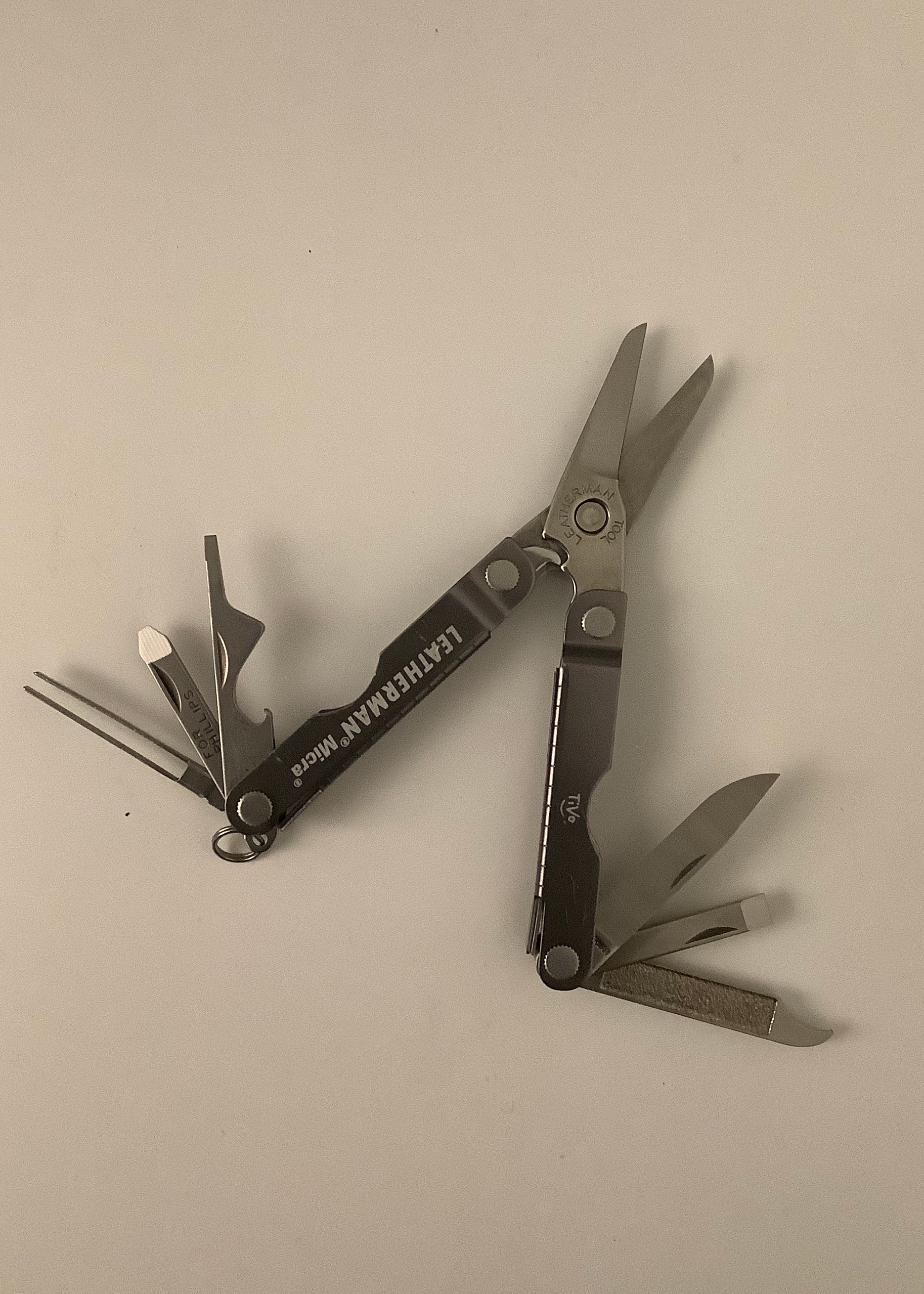
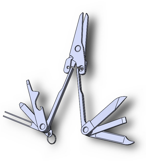
For this assignment, I decided to CAD my pocket knife! I chose this specific object because its mechanics allow all its parts and their relationships to be easily seen.
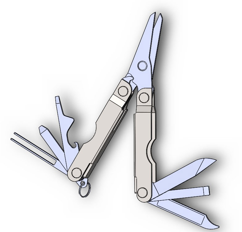
I made each part of the pocket knife that would be manufactured separately (the 2 handle cases, 6 blades, 2 scissor blades, ring, screws and bolts, scissor restrictor claw, and and another supporting layers). All these parts started as simple blocks of the right dimension and I basically just chipped away at and cut each part the way I thought it would be manufactured.
The geometries of the pocketknife were actually pretty simple and boxy. This made it easy to not only CAD but understand the step-by-step processes of manufacturing and assembling the knife. After CADing this knife from scratch, I would be confident in reassembling it from real parts.
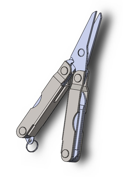
I also mated the parts so that their linear and rotational relationships were the same as in the real thing. I made sure to give a part a circular feature if I wanted to mate it concentrically to another part.
In taking a closer look at the pocket knife, I got to see what the restricting elements were and how each part was able to move. I was curious about the locking mechanism that made using the scissors without collapsing the whole knife possible. I discovered that this device uses an over center mechanism like the ones in levers and clamps with 2-bar linkages. This was a really cool realization, especially having learned about its physics in 2.001.
2D to 3D
Design a 3D object that can be constructed by press-fitting cut 2D shapes.
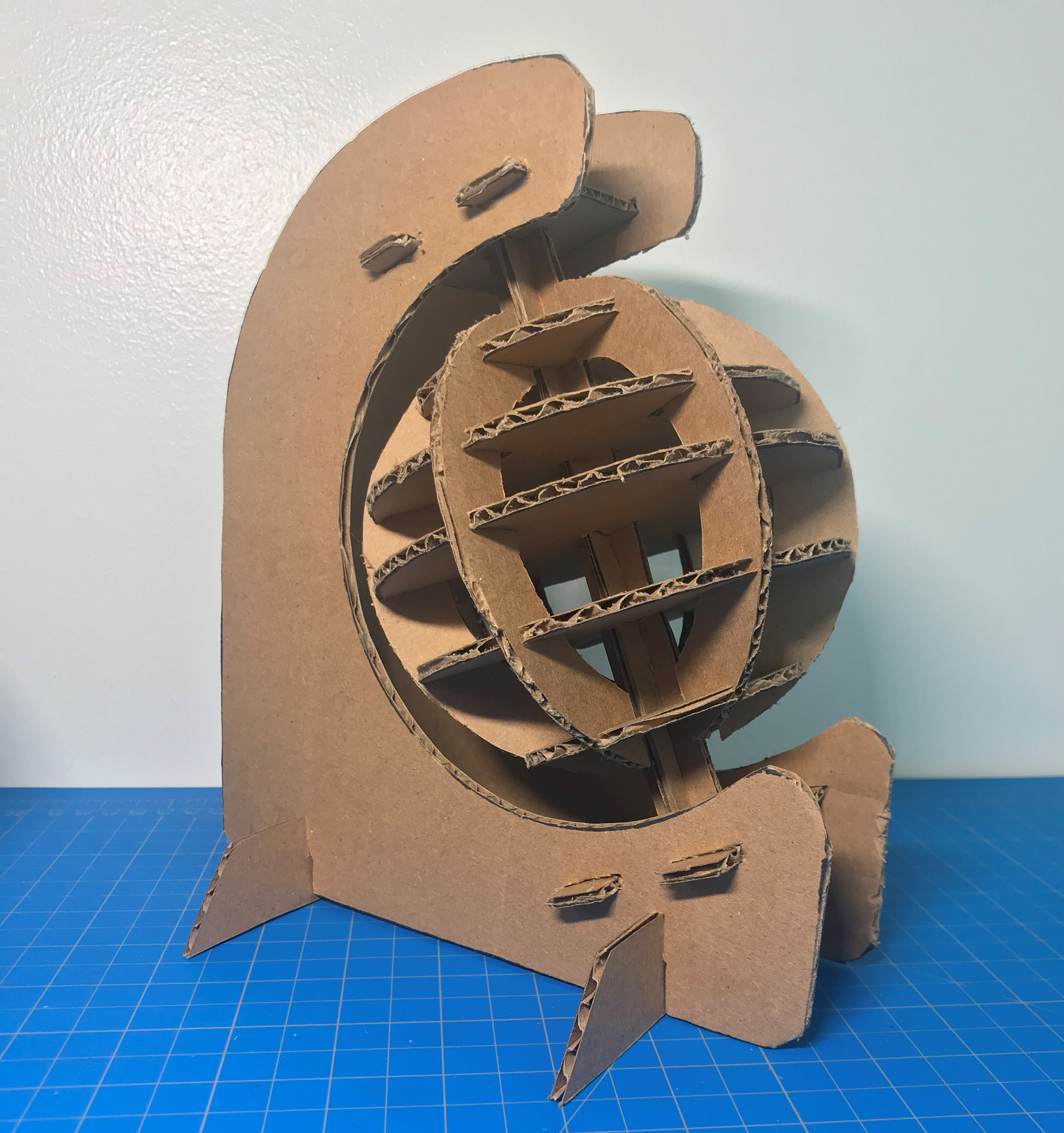
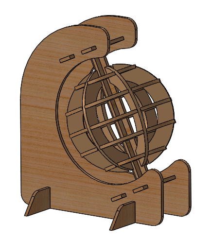
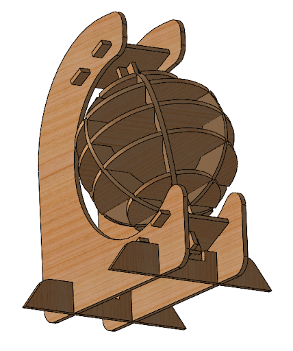
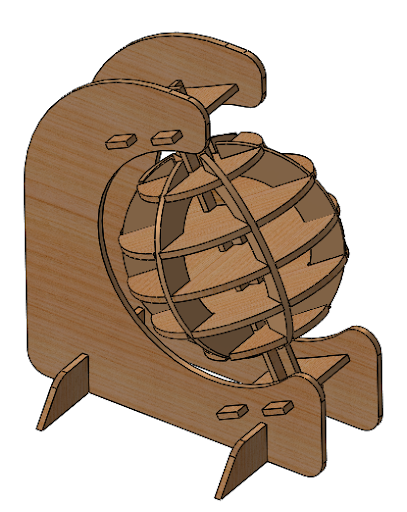
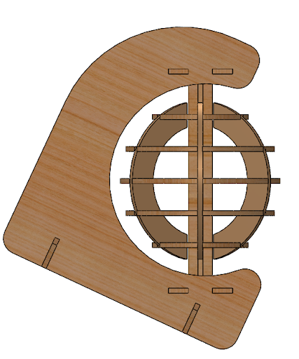
I decided to make a globe on a stand! Here is the CAD for it. The parts consist of concentric circles held together by crescent shapes that fit into slots in the circles. There is a center cross axle that runs through the middle of the globe. It is fit by halved lap joints. The cross axle then fits into two tabs at the top and bottom that connect it to the stand sides with four slots. The stand frames are stabilized with two bottom pieces that connect by half joints.

Profile
Tilted Up
Tilted Down
Side
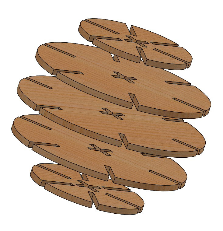
Concentric Disks
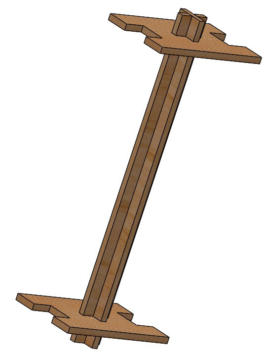
Axle and Tabs
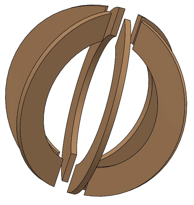
Crescent Supports
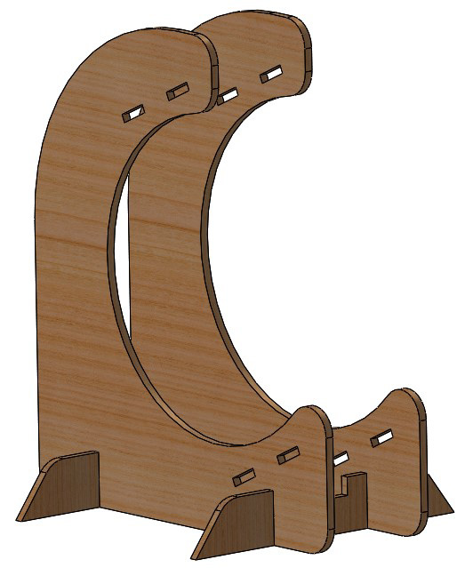
Stand
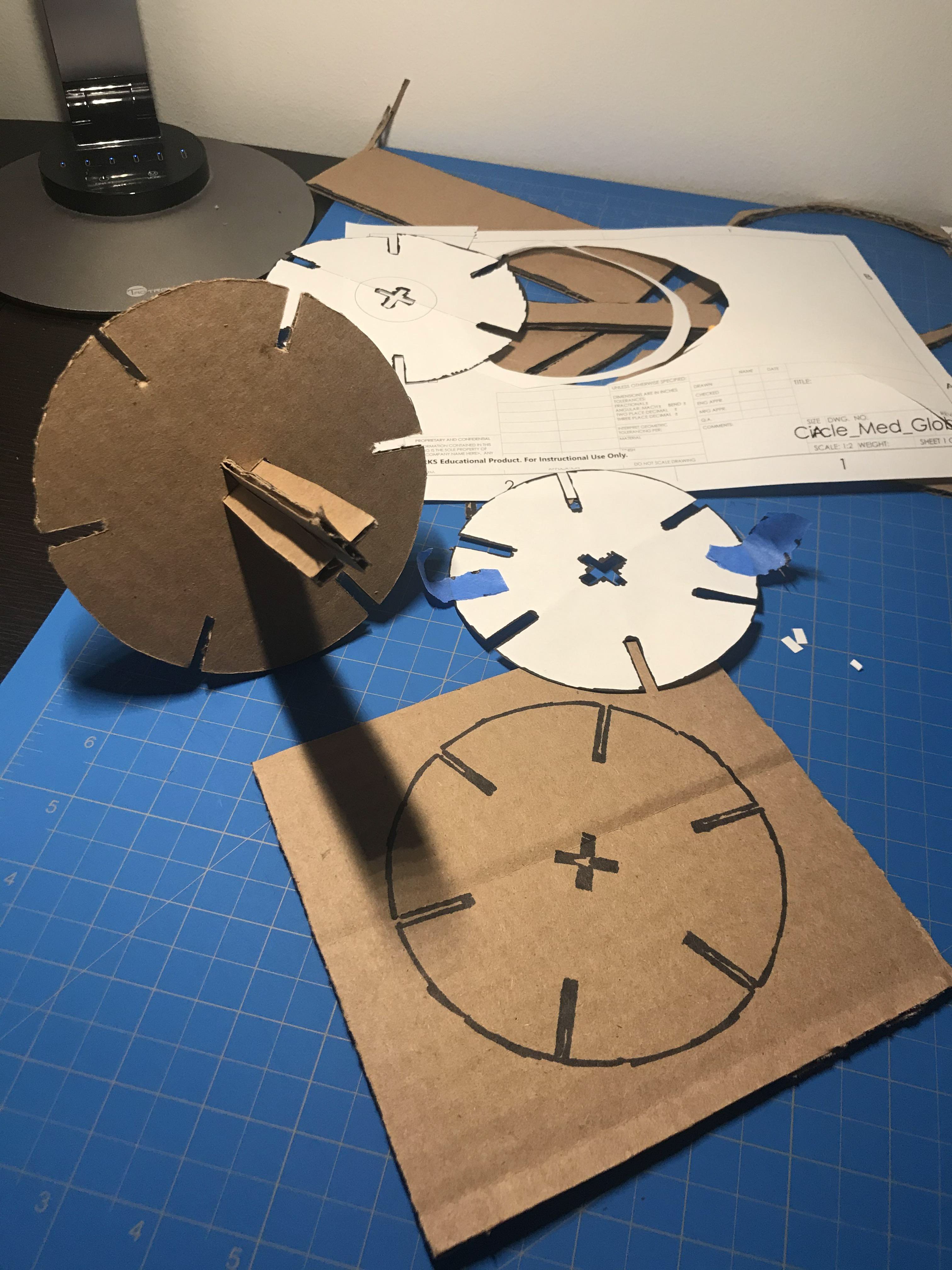
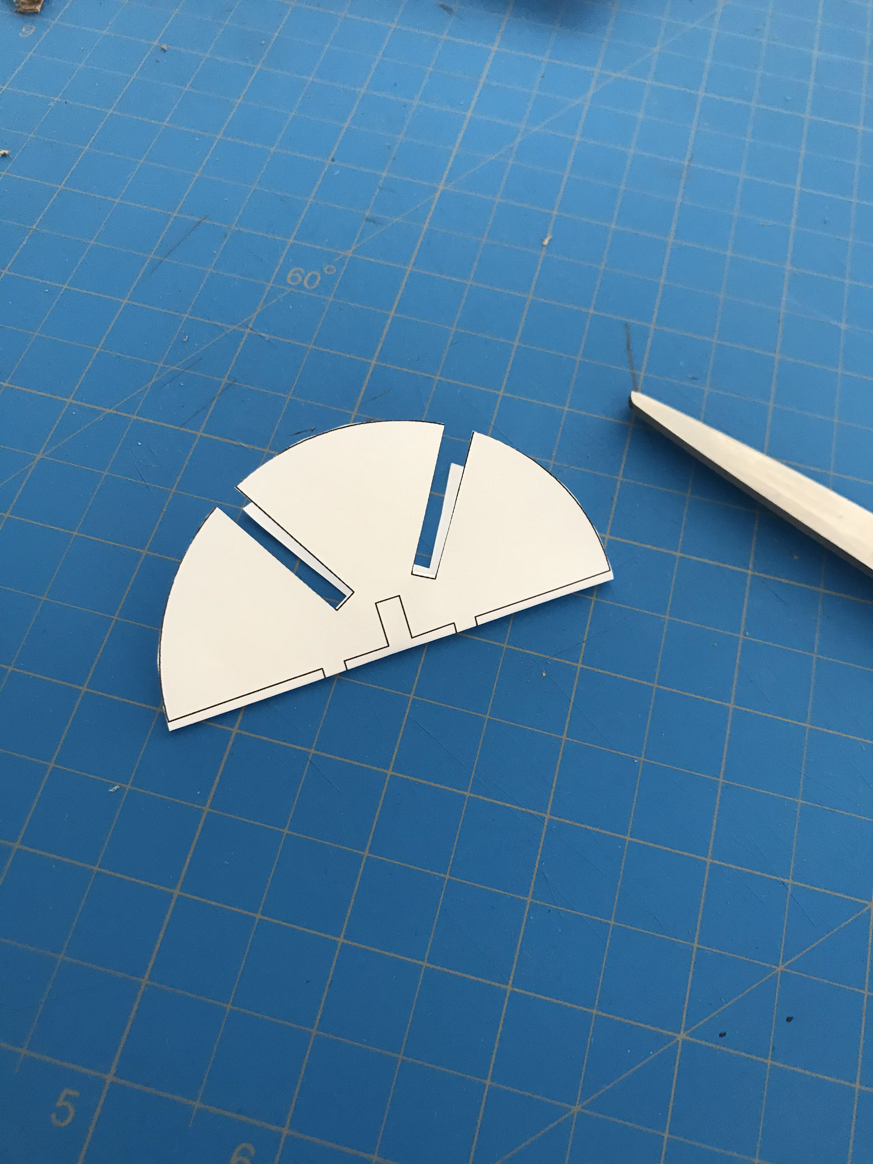
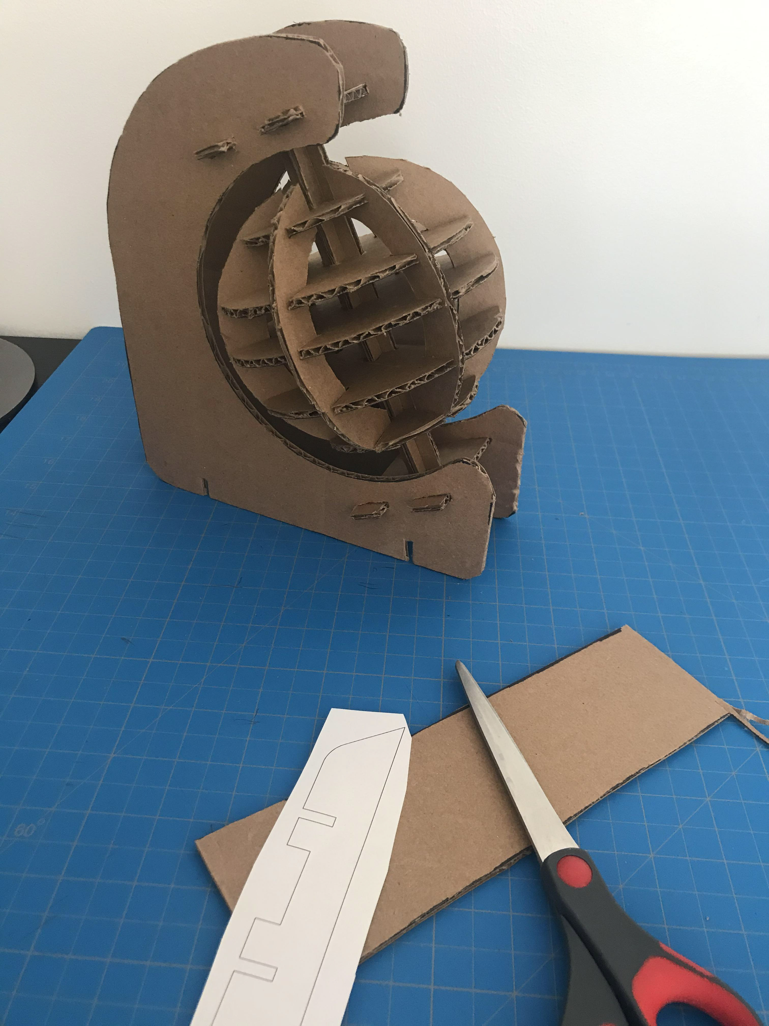
My strategy for manufacturing was to print out the sketch of each part, cut them out, and then trace them on the cardboard to cut out with my Olfa knife. This method worked well for every single piece.
To trace the slots that were in the center of the part, I had to fold the print so that I could cut it.
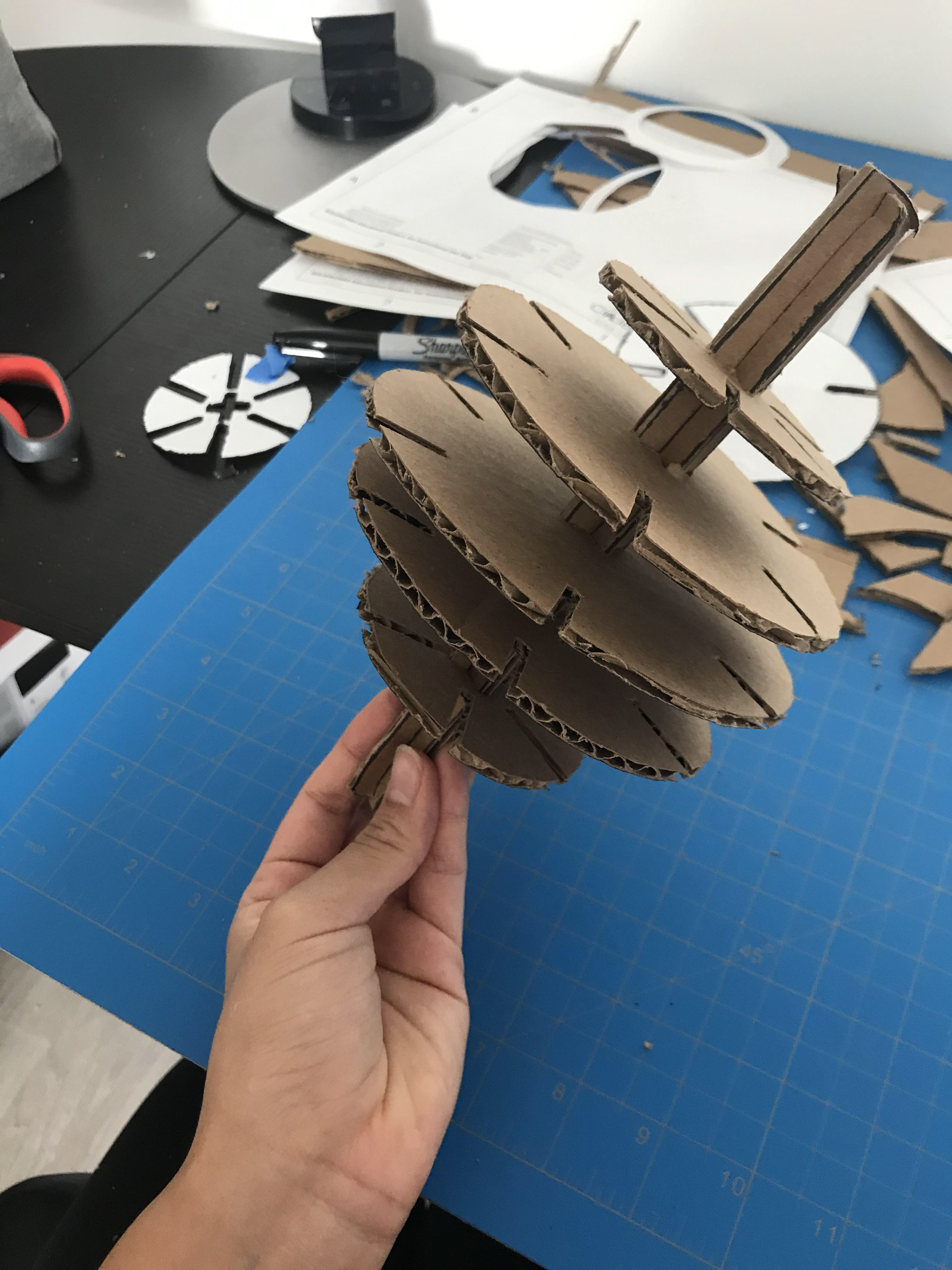
After making all the disks, I realized that the orientation of the disks so that the slots could line up was very important. even though the globe assembly is symmetric, the slots are not!
When it came time to building the legs, I realized that may not have been necessary! Nevertheless, extra support couldn't hurt. I made and added them anyway.
I am super pleased with my final design and how similar to my initial concept it turned out to be. Fitting the cardboard turned out the be easier than I had imagined and the part stays together very well.
Now I have a pretty globe for my desk. Maybe the next step could be making it spin!